SudoFlex
Programmable Digital Controller
DIY PLC PID Control Board
Easily Drag Drop
GUI
Package includes
* 1 pc SudoFlex Basic controller Board
* User Manual (Downloadable)
* SudoFlex Configurator GUI Software - Free (Downloadable)
(SudoFlex-Configurator only works on 64-bit Windows and Linux platforms for now)
*** Shipping ***
Free Standard Airmail Shipping with tracking number
Estimated Delivery Dates vary between 3-5 business days,
Introduction
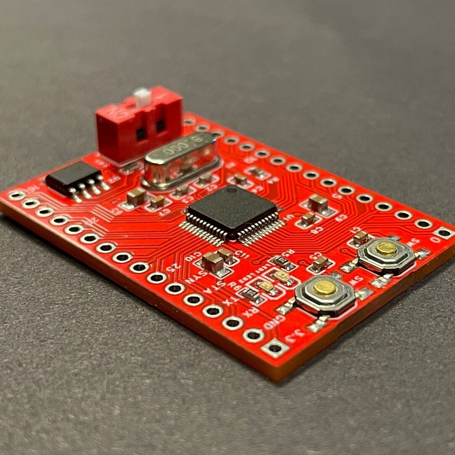
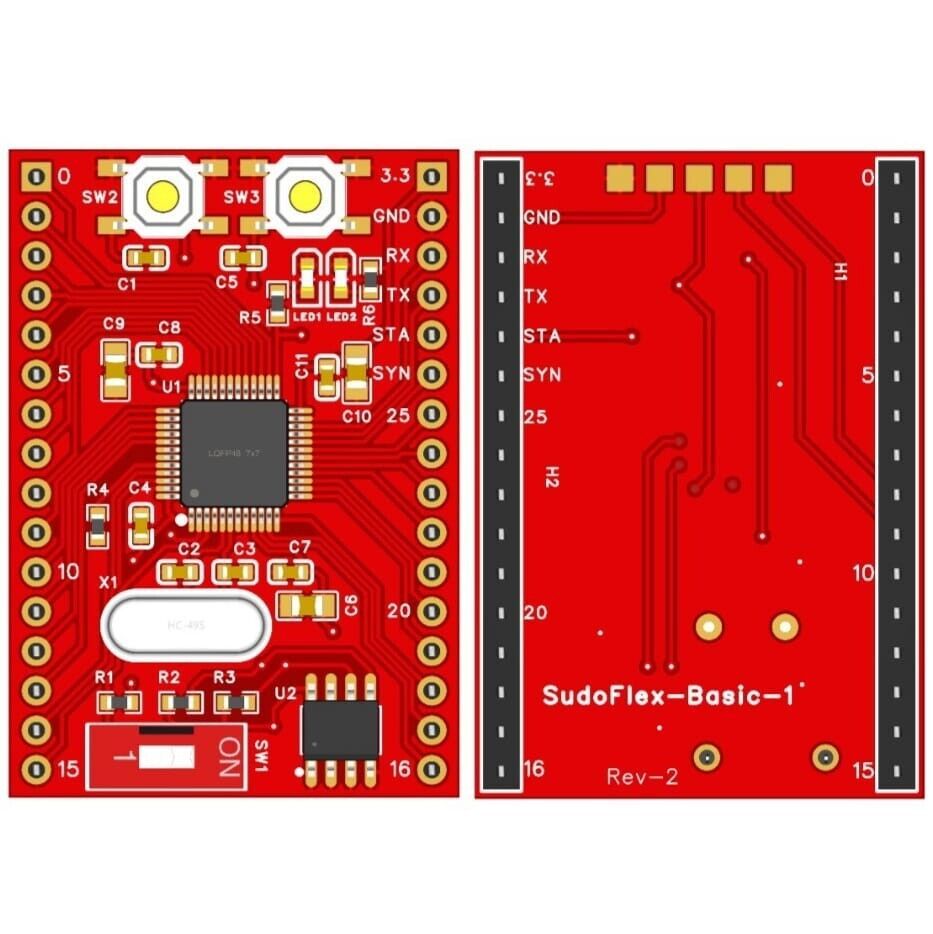
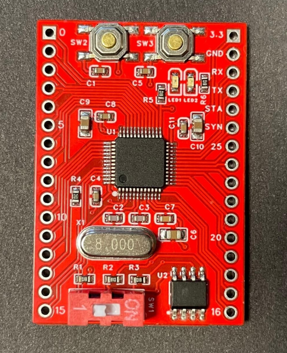
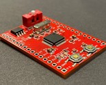
SudoFlex project aims to create a board family for digital control applications. SFB1 board is the first step of the project and the only available board in the market for now. This repository includes all necessary information and resources to start to use SFB1. Front and back views of the board are shown below.
Control algorithms for the board are developed by built-in blocks and block connections. There are 94 blocks for different functions. A summary of the blocks can be found below.
4 Type Conversion Blocks: F32_U32, U32_F32, F32_S32, S32_F32
4 Float Check Blocks: ISNAN, ISINF, ISFINITE, ISNORMAL
4 Rounding Blocks: CEIL, FLOOR, TRUNC, ROUND
15 Numerical Blocks: SQRT, CBRT, LN, LOG, LOG2, EXP, EXP2, SIN, COS, TAN, ASIN, ACOS, ATAN, ATAN2, ABS
14 Arithmetic Blocks: ADD, MUL, ADDC, MULC, SUB, DIV, MOD, FMOD, REMAINDER, EXPT, HYPOT
SMA: Simple Moving Average
CMA: Cumulative Moving Average
EMA: Exponential Moving Average
8 Bitwise Operation Blocks: SHL, SHR, ROL, ROR, BITAND, BITOR, BITXOR, BITNOT
5 Selection Blocks: MAX, MIN, LIMIT, SEL, MUX
6 Comparison Blocks: GT, GE, LT, LE, EQ, NE
6 Logic Blocks: NOT, AND, OR, XOR, ANDBFOR, ORBFAND
2 Flip-flop Blocks:
SR: Set dominant flip-flop
RS: Reset dominant flip-flop
2 Edge Detection Blocks:
R_TRIG: Rising edge detection
F_TRIG: Falling edge detection
3 Counter Blocks:
CTU: Up counter
CTD: Down Counter
CTUD: Up-down counter
3 Timer Blocks:
TON: On-delay timer
TOF: Off-delay timer
TP: Pulse timer
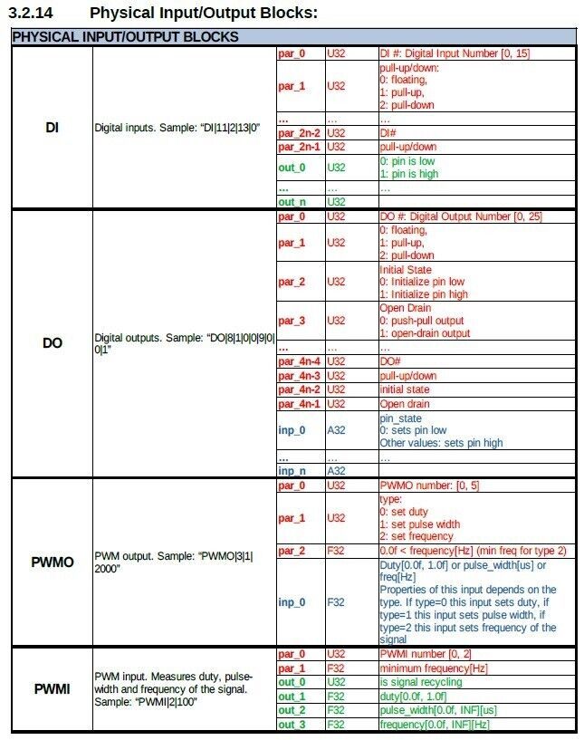
6 I/O Blocks:
DI: Digital input
DO: Digital output
PWMO: PWM output
PWMI: PWM input
ENC: Incremental encoder input
AI: Analog input
5 Source Blocks:
CONST: Constant numbers
CAPTURE: Captures input values when triggered
TIME: Provides time value in terms of sampling period
WAVE: Generates custom defined wave
PULSE: Pulse generator. Useful for step motor driving.
5 Control Blocks:
UDELAY: Unit delay, delays input for one sampling period
TFD_1: First-order discrete transfer function
TFD_2: Second order discrete transfer function
TFD_3: Third-order discrete transfer function
PID: PID controller with anti-windup and derivative filter
1 Connectivity Block:
MODBUS_RTU: Modbus RTU communication
Other Blocks: PAUSE
For a detailed reference information about SFB1 you can refer to the user manual in pdf format. Latest user manual can be found under Releases section.
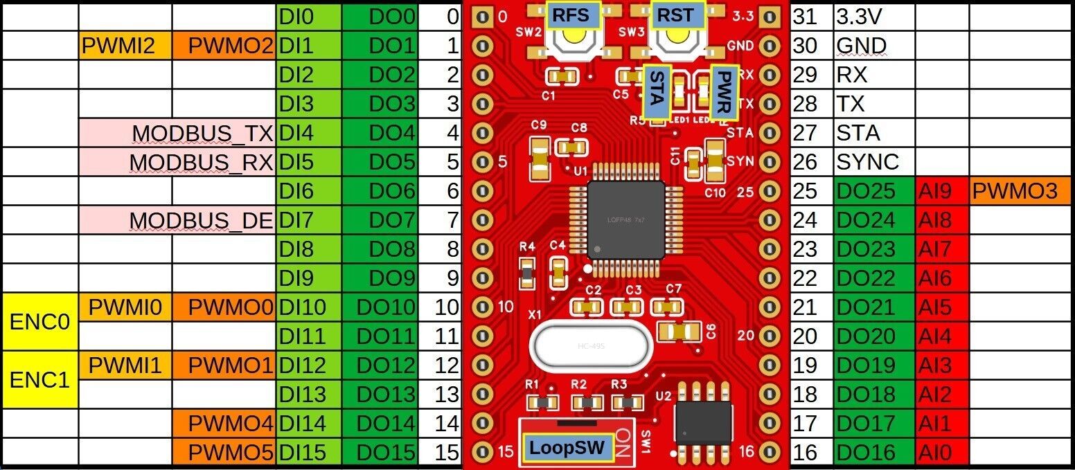
Pin Mapping and Button/Led Definitions
Pin mapping and button/led definitions can be seen on the table below.
Abbreviation
Description
DIx
Digital Input pins
DOx
Digital Output pins
PWMIx
PWM Input pins
PWMOx
PWM Output pins
ENCx
Incremental Encoder Input pins
AIx
Analog Input pins
AOx
Analog Output pins
MODBUS_xx
Modbus RTU pins
SYNC (26)
Synchronization pin. This pin goes high at the start of sampling and stays high during algorithm execution. So signal frequency is equal to sampling frequency and signal pulse width shows the algorithm execution time.
STA (27)
If algorithm execution time exceeds sampling period this pin goes high. It is also connected to STA led.
TX, RX (28, 29)
UART Programming Interface pins for SFB1
GND (30)
Ground pin for SFB1
3.3V (31)
Power pin for SFB1. Applied voltage must not exceed 3.3V and should be regulated.
RFS
Return to factory settings button. If this button is pressed during reset, board clears the saved algorithm and returns to default algorithm string.
RST
Reset button
LoopSW
Loop on-off switch
PWR
Power led
STA
Status led. This led turns on if sampling frequency is too high for the current algorithm execution or sampling frequency is zero.
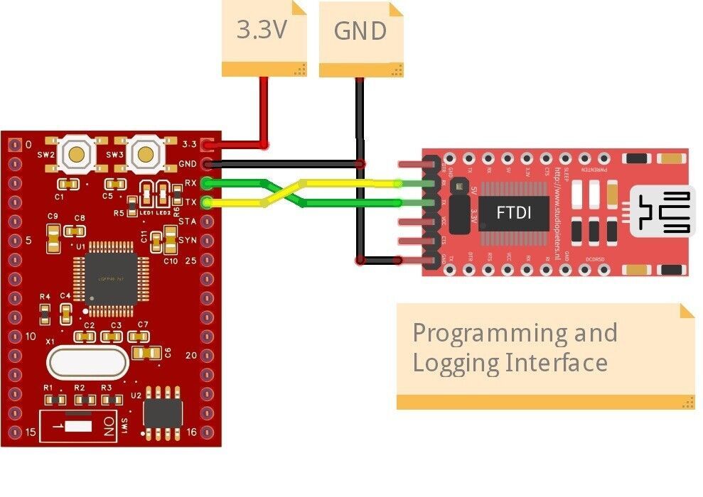
Minimum Connections
In order to start developing with SFB1 board, one has to make minimum connections as shown on the figure below. First, regulated 3.3V power must be supplied to the board. Second, a UART-USB converter board should be connected to the SFB1 board to make a programming and logging interface connection with SudoFlex-Configurator running on the computer. UART-USB converter boards are common in the market and can be obtained easily at reasonable prices. Both FTDI and CH340 based boards are perfectly convenient, however CH340 based boards may need driver installation.
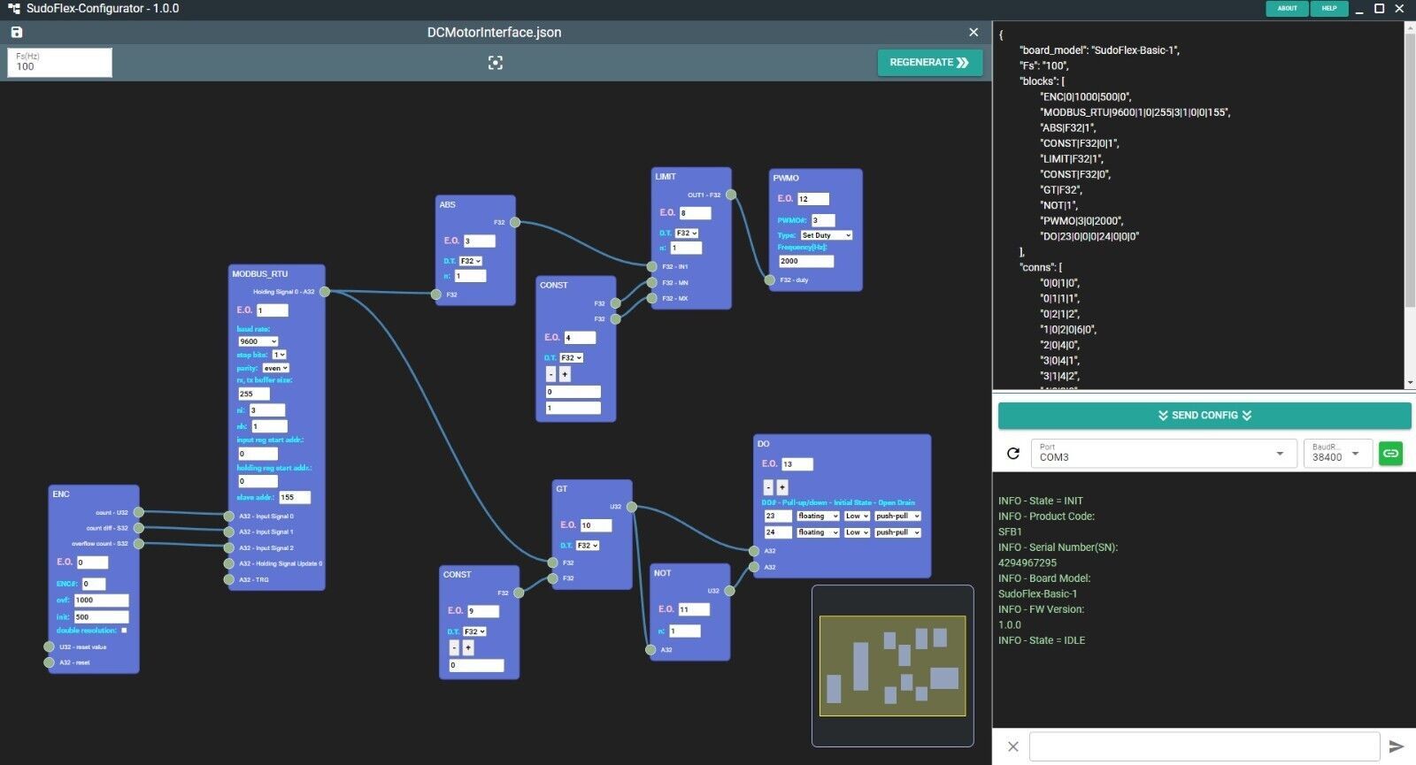
SudoFlex-Configurator
SudoFlex-Configurator is a desktop GUI application used for developing control algorithms. It has also a serial interface that can be used for downloading generated algorithms to the board and tracing log messages. A screenshot of the application can be seen on the figure below.
SudoFlex-Configurator only works on 64-bit Windows and Linux platforms for now. Under Releases section, there are 3 application files:
SudoFlex-Configurator.Setup.1.x.x.exe: Setup file for Windows installation.
SudoFlex-Configurator.1.x.x.exe: Portable Windows application file for users that want to use the application without installation.
SudoFlex-Configurator-1.x.x.AppImage: Linux application file
Notes for Windows users
You can use setup file for installing SudoFlex-Configurator as a regular Windows desktop application. SudoFlex-Configurator is a self-signed application. Therefore, Windows may try to block installation by Smart Screen. You can continue installation by clicking "More info" text.
If you don't want to install SudoFlex-Configurator, you can use the portable application file. You can directly run the application by running this file. Unfortunately again, Smart Screen may block you running the application.
Notes for Linux users
.AppImage file is the self-contained application file for Linux. You can directly download this file, make it executable, and run the application in Linux.
SudoFlex-Configurator needs a serial port connection to communicate with the board. Therefore, you need to add the user to the "dialout" group under Linux. Following command can be used for this purpose:
sudo usermod -a -G dialout username
Also, access permisions of the port may need to be changed under Linux. For example, following command can be used to change the access permisions of ttyUSB0:
sudo chmod a+rw /dev/ttyUSB0
Examples
7 introductory examples are prepared for a gentle introduction to SFB1. Json files of the examples can be found under the "examples" folder. These examples demonstrate the basic I/O and communication features of SFB1. After this introduction, SFB1 user manual should be used for detailed information about other blocks board features.
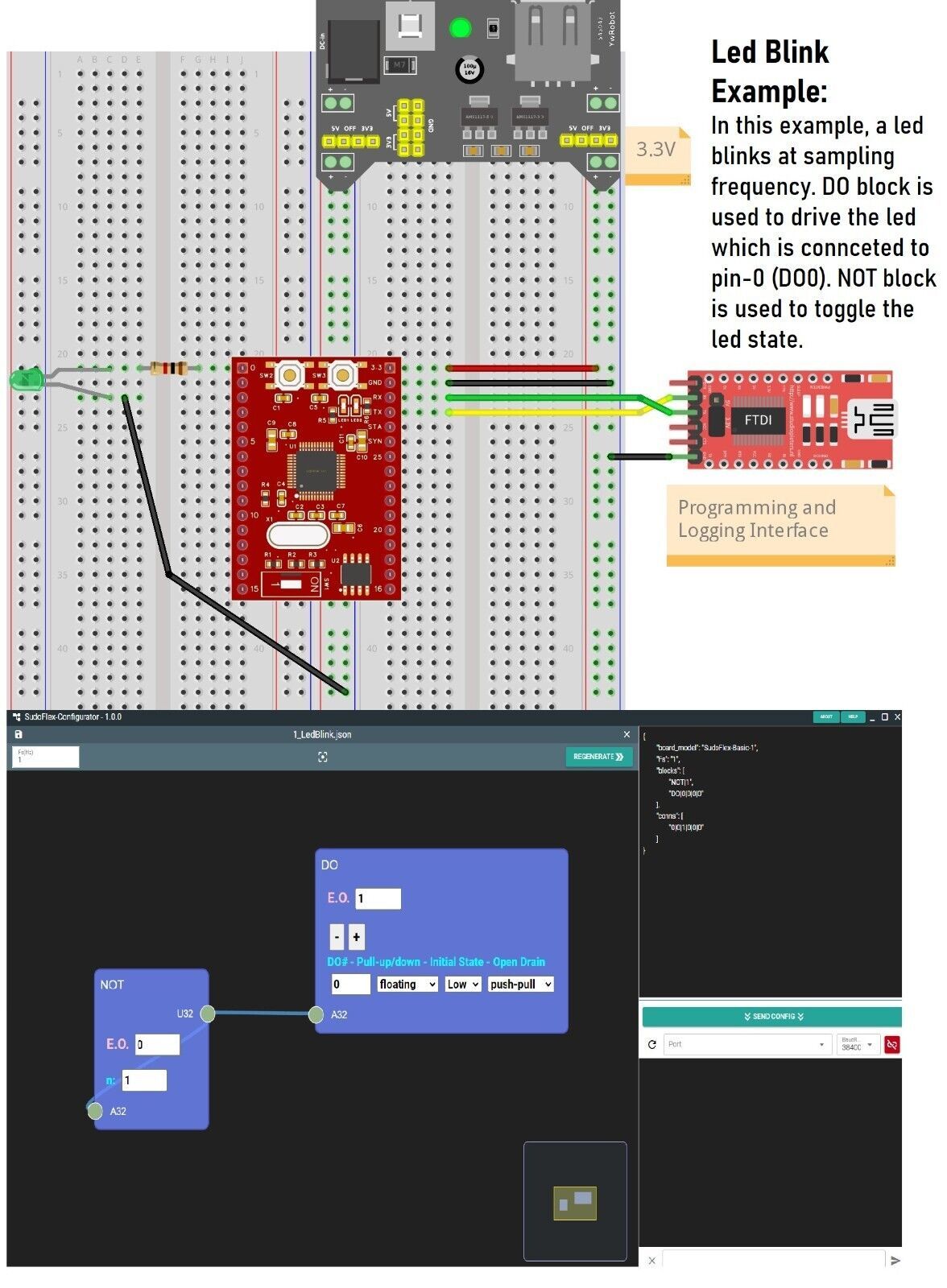
1-Led blink
In this example, a led blinks at sampling frequency. DO block is used to drive the led which is connceted to pin-0 (DO0). NOT block is used to toggle the led state.
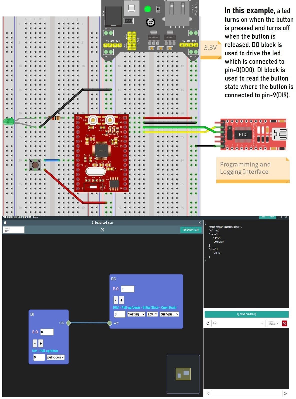
2-Button/led interface with DI and DO
In this example, a led turns on when the button is pressed and turns off when the button is released. DO block is used to drive the led which is connected to pin-0(DO0). DI block is used to read the button state where the button is connected to pin-9(DI9).
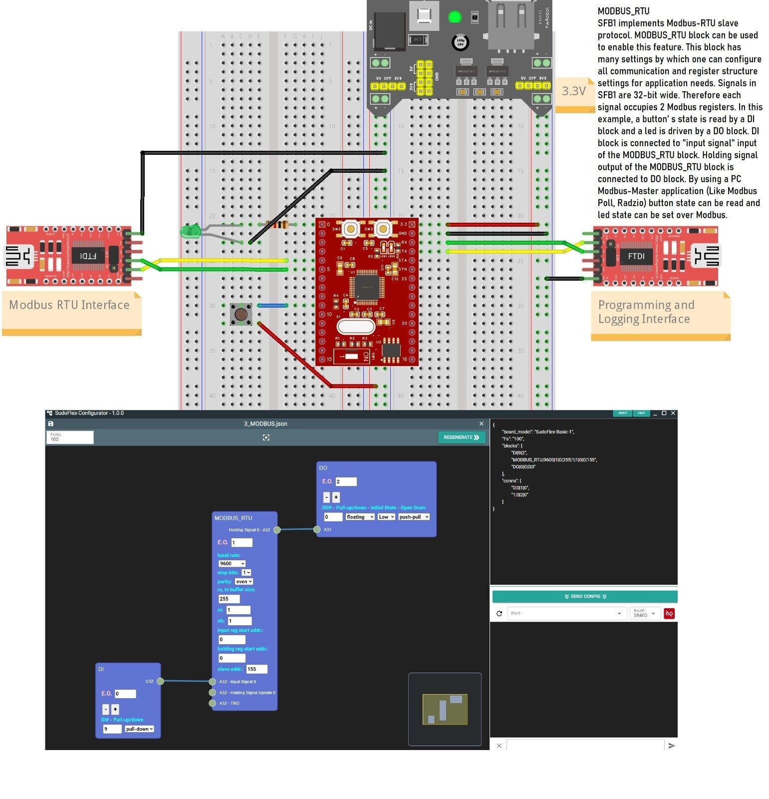
3-MODBUS_RTU
SFB1 implements Modbus-RTU slave protocol. MODBUS_RTU block can be used to enable this feature. This block has many settings by which one can configure all communication and register structure settings for application needs. Signals in SFB1 are 32-bit wide. Therefore each signal occupies 2 Modbus registers. In this example, a button' s state is read by a DI block and a led is driven by a DO block. DI block is connected to "input signal" input of the MODBUS_RTU block. Holding signal output of the MODBUS_RTU block is connected to DO block. By using a PC Modbus-Master application (Like Modbus Poll, Radzio) button state can be read and led state can be set over Modbus.
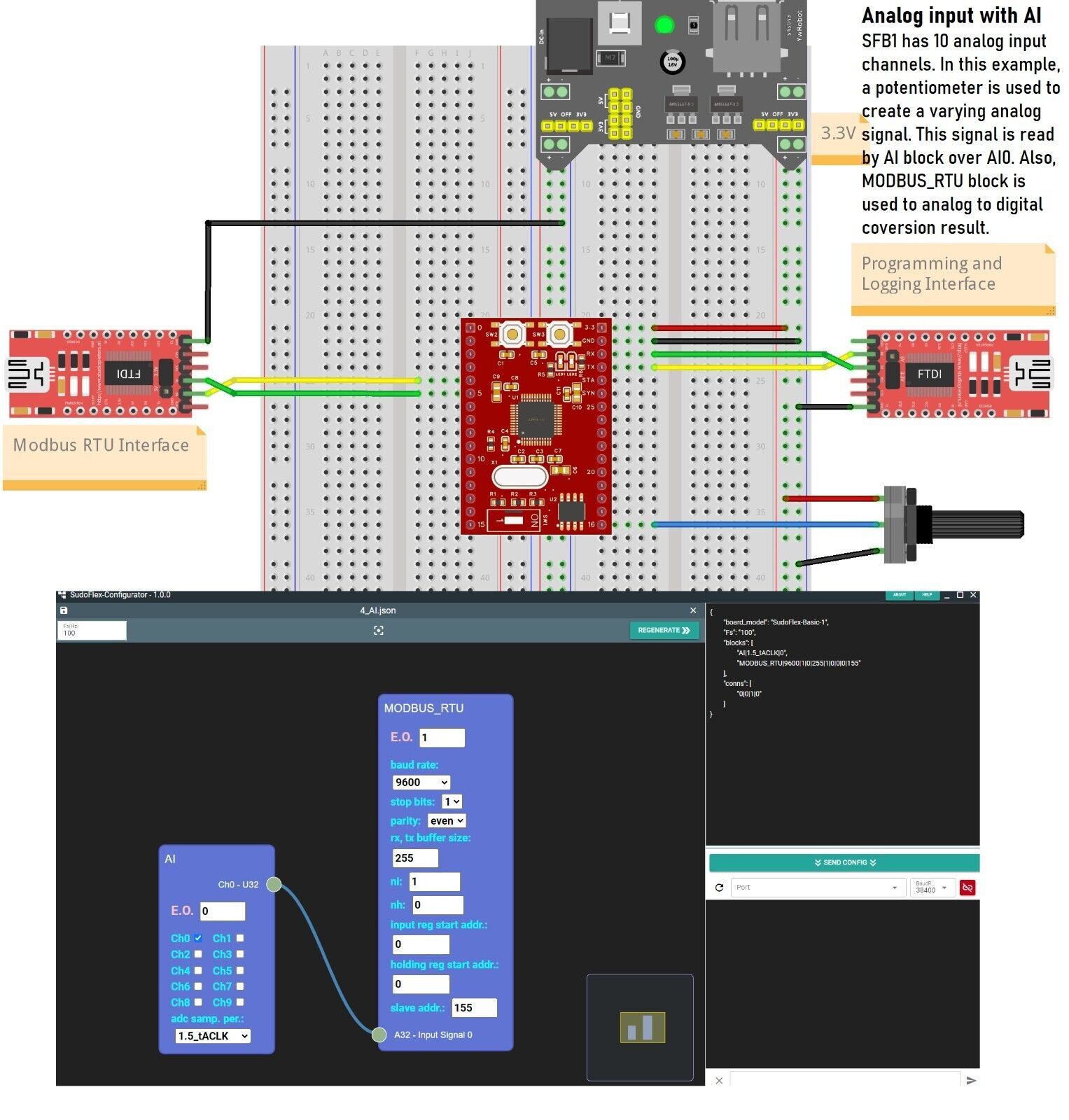
4-Analog input with AI
SFB1 has 10 analog input channels. In this example, a potentiometer is used to create a varying analog signal. This signal is read by AI block over AI0. Also, MODBUS_RTU block is used to analog to digital coversion result.
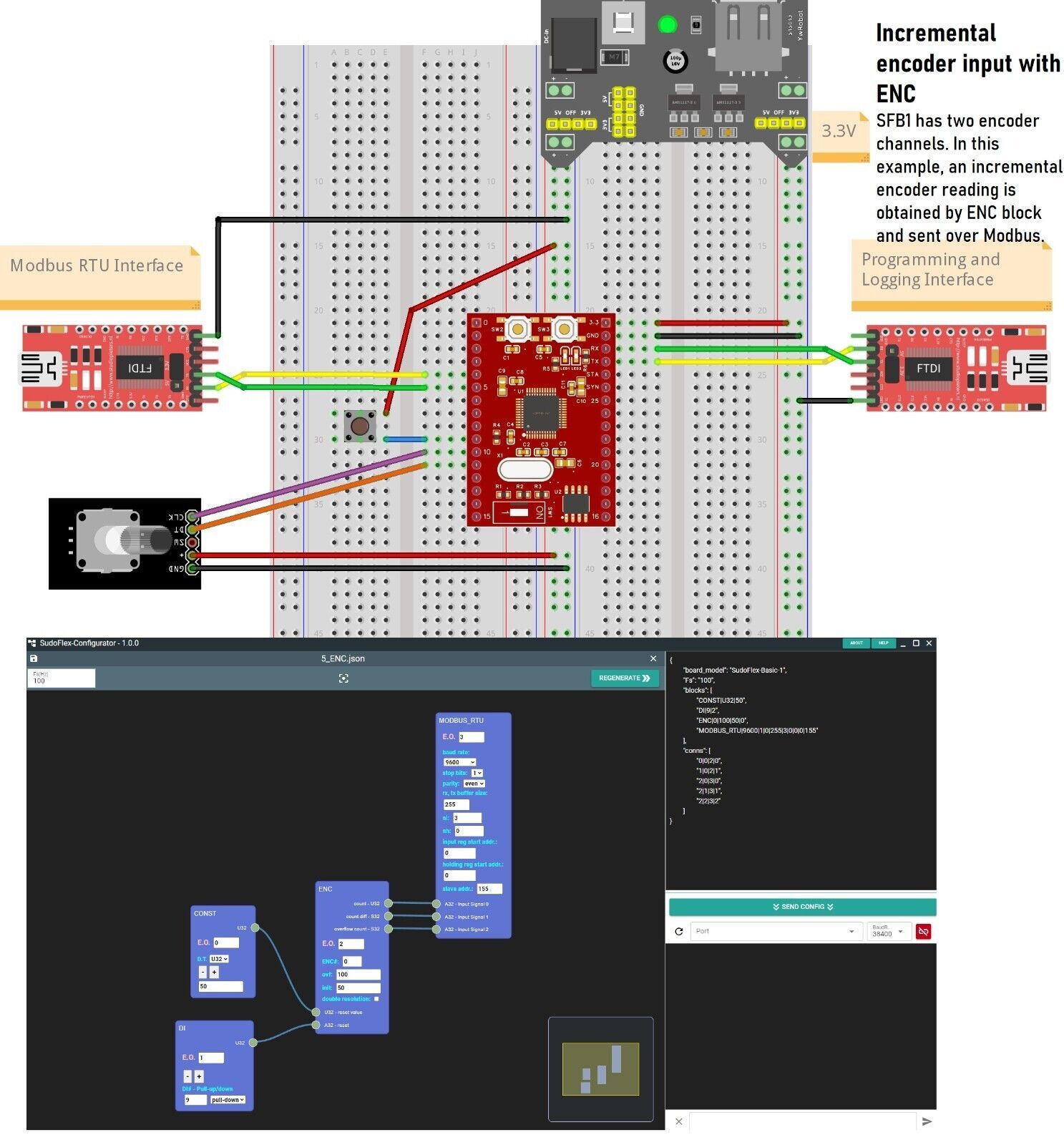
5-Incremental encoder input with ENC
SFB1 has two encoder channels. In this example, an incremental encoder reading is obtained by ENC block and sent over Modbus.
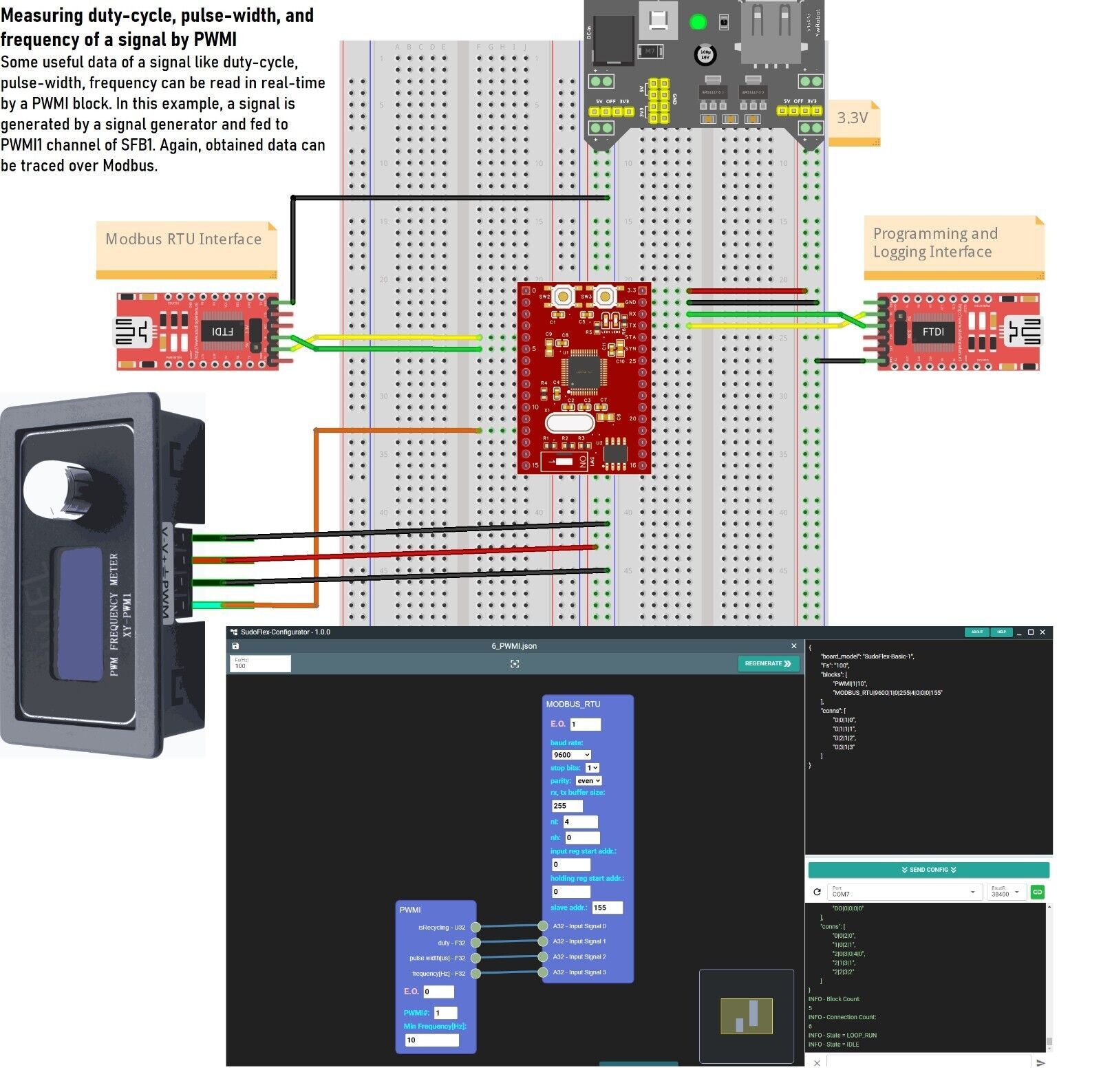
6-Measuring duty-cycle, pulse-width, and frequency of a signal by PWMI
Some useful data of a signal like duty-cycle, pulse-width, frequency can be read in real-time by a PWMI block. In this example, a signal is generated by a signal generator and fed to PWMI1 channel of SFB1. Again, obtained data can be traced over Modbus.
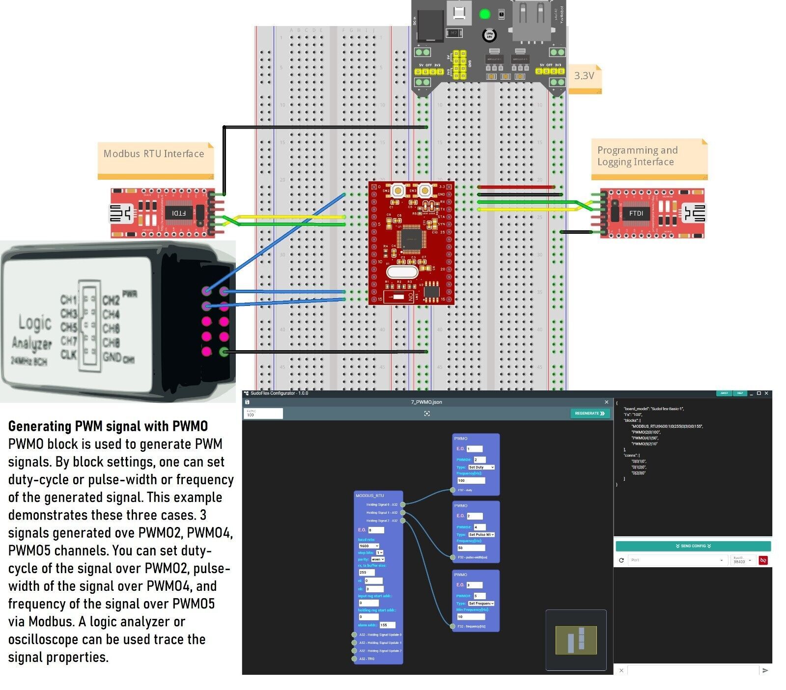
7-Generating PWM signal with PWMO
PWMO block is used to generate PWM signals. By block settings, one can set duty-cycle or pulse-width or frequency of the generated signal. This example demonstrates these three cases. 3 signals generated ove PWMO2, PWMO4, PWMO5 channels. You can set duty-cycle of the signal over PWMO2, pulse-width of the signal over PWMO4, and frequency of the signal over PWMO5 via Modbus. A logic analyzer or oscilloscope can be used trace the signal properties.
**** Payment ****
All Orders will be post within 1 working days after received Clear Payment,
All items request immediate payment.
Import duties, taxes and all other extra charges are the buyer's responsibility. These costs are not included in the price or shipping cost. Please check your customs regulations if you have any concerns.
If there is Free Gift on Publish, according to stock, brand may change but quantity will be same.
If you do not receive your shipment within 35 days from giving to postage, please contact us. We will refund or send it again, Our goal is customer satisfaction!
We are not responsible for wrong or undeliverable address. Please check your address before checkout.
Item which you are interested in, is as it seems on the photos, if you need more information more than we publish, please send us E-Mail, we will reply you as soon as possible.
(description exceeds maximum possible length)