|
API Aeroflex Weinschel 3206T-1E Programmable Attenuator 0-3GHz 1-63dB range step
We gladly ship Worldwide*
Scroll down for more Photos and details
|
|
Attenuation Range/Steps (dB) 127/1
Cell Increments ( dB) : 1, 2, 4, 8, 16, 32, 64*
MAXIMUM INSERTION LOSS (dB):
Frequency Range (GHz)
3206T-1E :
dc - 0.5 GHz 2.20
0.5 - 1.0GHz 2.40
1.0 - 1.5GHz 2.80
1.5 - 2.0GHz 3.10
2.0 - 3.0GHz 3.70
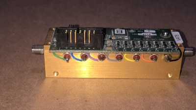
Description
This line of intelligent programmable step attenuators with a
built-in digital interface are designed to simplify the control
and integration of these devices into subsystem and bench
applications. This series of Programmable Step Attenuators
is designed for use in automatic test equipment and OEM
systems operating in the dc to 3 GHz frequency range.
These models are available in many standard attenuation
ranges and cell configurations. Each cell contains a doublepole,
double-throw relay that provides a minimum loss or
attenuated path for the RF signal.
Microstrip circuitry and special compensation techniques
produce flat attenuation versus frequency characteristics.
To minimize RF leakage, the 3200T Series Attenuators are
provided with gold-plated contact areas and feedthrough filters
at each control terminal.
Part Number:
3206T-1E
Manufacturer:
API/Weinschel/Aeroflex
Frequency Min:
0 GHz
Frequency Max:
3 GHz
dB Value:
63 dB
Avg. Power:
1 W
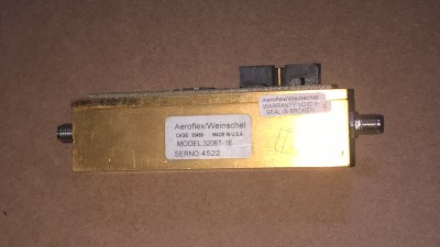
Connector 1:
SMA Female
Connector 2:
SMA Female
Length:
1 in
Specifications
NOMINAL IMPEDANCE: 50
FREQUENCY RANGE: dc to 3.0 GHz
MONOTONICITY: 10 MHz to 3.0 GHz
(minimum 1 dB change)
POWER COEFFICIENT: <0.002 dB/dB/watt
INCREMENTAL TEMPERATURE COEFFICIENT:
30 & 32 dB cells: 0.0005 dB/dB/
POWER RATING: 1 watt average to 25ambient temperature,
derated linearly to 0.25 watt @ 71. 50 watts
peak (5 pulse width; 1% duty cycle)
RATED SWITCH LIFE: 5 million cycles operations per cell
@ 0 dBm
CYCLING RATE: 5 Hz maximum per relay
DRIVER INTERFACE:
Input Supply Voltage: +12.0 to +15 V
Control Signals:
Interface Modes:
DC Characteristics (at 25 ):
Parameter
VIL Low-level input V:
VIH High-level input V:
I
PU Pullup current
VIN Supply Voltage:
I
IN Supply current:
(digital section)
I
CELL Supply current:
TTL/CMOS compatible
parallel / serial
Specification
-0.5 V min, 0.8 V max
2.0 V min, 5.25 V max
50 min, 400 max
+12.0 to +15.0 V
25 mA
15 mA typical per cell
continuous
TEMPERATURE RANGE (Operating): -20to +70
TEST DATA: Test data is available at additional cost.
CONNECTORS: SMA female connectors per MIL-STD-348
interface dimensions - mate nondestructively with
MIL-C-39012 connectors.
INTERFACE CONNECTOR: 14 pin .025 square post
header on .1 center. Mates with Amp connector 746285-2 or
equivalent.
CONSTRUCTION:
Housing: Aluminum
Connectors: Stainless steel body and beryllium
copper contacts.
Don't forget to place your bid.
More photos down below
|
|
|
on this sale you agree to the following terms:
Shipping Terms:
Payment Terms:
International Terms: (These terms only apply to international shipments.)
Warranty Terms:
Return Terms:
Medical Device Terms:
The following terms apply to any and all medical items or any item offered for sale in any medical category or any item that deems these terms are applicable to:
Item Condition Terms:
On these listings, our company's condition "used" does NOT necessarily mean "fully operational and functions as intended". If fact it may have unknown flaws and deficiencies. the item has only been tested to the extent described in the item condition/testing notes. Additional testing may be performed upon request of the buyer before shipment to ensure a satisfactory transaction for both parties.
If any provision of this sale Contract is held unenforceable, All remaining provisions of this Contract shall remain in full force and effect.
Copyright 2018 bizbonanza- All Rights Reserved.
|